Abstract
A Proportional-Integral-Derivative (PID) controller was designed for a one-degree-of-freedom helicopter allowed to rotate by an angle \(\theta\) in a vertical plane. The controller was designed using an Arduino Uno such that the user can specify the desired angle at which the helicopter is to fly. The proportional, integral, and derivative gains were chosen such that the range at which the controller works is maximized. The project ultimately demonstrated how PID controllers are an effective way to implement feedback control in a system where the physical hardware is accessible and can be tuned.
I. Introduction
Feedback controllers allow systems to be modified such that they output a controlled variable that tracks a user-defined reference. The output of the system is fed back into the controller, allowing the controller to calculate the error between the reference input and the system output. The system for this project is a one-degree-of-freedom helicopter that rotates by an angle \(\theta\). A proportional-integral-derivative (PID) controller was implemented and tuned to allow the user to input a reference angle that the system effectively tracks. The necessary background required for this paper is discussed is in Section II. Section III discusses the mechanical apparatus as well as the circuitry that enabled the controller to be designed. In Section IV, the method by which the gains for the PID controller are selected is discussed, as well as the corresponding results. Section V provides explanations to the phenomenon discovered in Section IV. Section VI concludes the objective and findings of the project.
II. Background
The objective was to design a controller that would enable the helicopter to fly to a user-defined input angle.
 Figure 1. Control block diagram for helicopter system. The controller takes in error computed from the actual \(\theta\) and the desired \(\theta\), and outputs a voltage. The plant takes in the voltage, causes the motor spin to change, and outputs a new actual angle \(\theta\).
The type of controller chosen was a PID controller. For an error given by \(e = \theta_{des} - \theta_{actual}\), the output of a PID controller is given by:
\[\text{control output} = K_pe(t) + K_i \int dt(e(t)) + K_d \frac{d}{dt}e(t)\]A controller’s effect on the system can be characterized by 4 quantitative measurements: steady-state error, rise time, overshoot, and settling time, illustrated in Fig. 2.
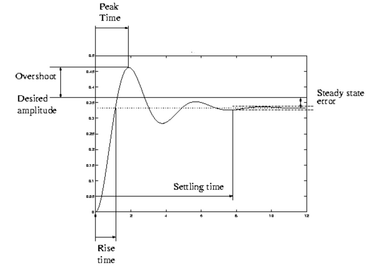 Figure 2. Plot illustrating definitions of overshoot, rise time, settling time, and steady-state error. Adapted from [4].
The steady-state error is defined as the difference between the steady-state response of the system and the reference input. Rise time is quantified by the time it takes to increase to the final steady-state value. Overshoot is the difference between the highest peak and the desired output. Settling time is defined as the time it takes the output to settle to within 2% of the final value [4].
III. Apparatus and Circuitry
Mechanical Apparatus
The apparatus for the mechanical implementation of the helicopter is shown in Fig. 3. The helicopter was constructed of a motor (part A) hot glued to the end of a stiff wooden rod (part B) such that the rotor blades are parallel to the wooden rod. The other end of the wooden rod was hot-glued to a knob (part C) that could interface with a potentiometer (part D). The subsystem of parts A, B, C, and D was provided pre-assembled by V. Hunter Adams [1].
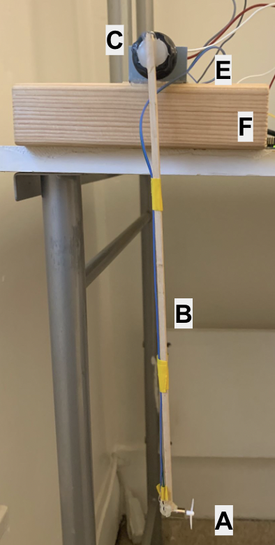 Figure 3. Apparatus for project, showing the DC helicopter motor and blades (A), wooden rod (B), black knob to interface with potentiometer (C), 10 \(k \Omega\) potentiometer (D), potentiometer mounting bracket (E), 4x2x6 wooden block (F).
The mounting system was constructed of a metal bracket (part E) that could house the potentiometer in a stable position. The metal bracket was screwed onto a plank of wood (part F). Finally, the black knob was tightened onto the potentiometer, thus generating a full assembly of the mechanical components, as shown in Fig. 3. The mechanical system allowed the helicopter to rotate in the plane of the page by an angle \(\theta\).
Electrical Circuitry
The first aspect of generating the circuitry was to enable the motor to spin at different rates based on an input signal. This was accomplished using the circuit diagram shown in black in Fig. 4. The current flows from the power source on the right, through the motor, and to ground. The PWM input signal from the Arduino determines how much current is enabled to flow through the transistor and therefore the motor. Thus the circuit allows the Arduino to be programmed such that it can output a PWM signal that directly corresponds to the motor spin speed.
 Figure 4. Circuit designed to spin the induce variable motor spin based on an input pulse-width-modular (PWM) signal, pulled from [2]. The values for the electrical components are tabulated in table I.
The second aspect involved providing the Arduino with an input signal that encoded information about the helicopter angle. The black knob is securely mounted onto the potentiometer such that when the helicopter rotates by an angle \(\theta\) the potentiometer is rotated by an equivalent angle. Thus the potentiometer corresponds linearly with the helicopter angle. The red portion of the circuit in Fig. 4 shows the potentiometer circuit. The potentiometer outputs an analog signal that is converted to digital using the Analog-to-Digital Converter (ADC) built-in on the Arduino.
| Component | Description |
|---|---|
| Motor | DC |
| Diode | IN4001 |
| Resistor | $$270\Omega$$ |
Table I. Electrical Components
The digital values output by the potentiometer were mapped to corresponding angles by manually taking data points while the motor was off. The helicopter was held at \(0^{\circ}\), \(90^{\circ}\), and \(180^{\circ}\) and the corresponding potentiometer value was read from the Arduino. The data was fit to a linear line of best fit, as shown in Fig. 5.
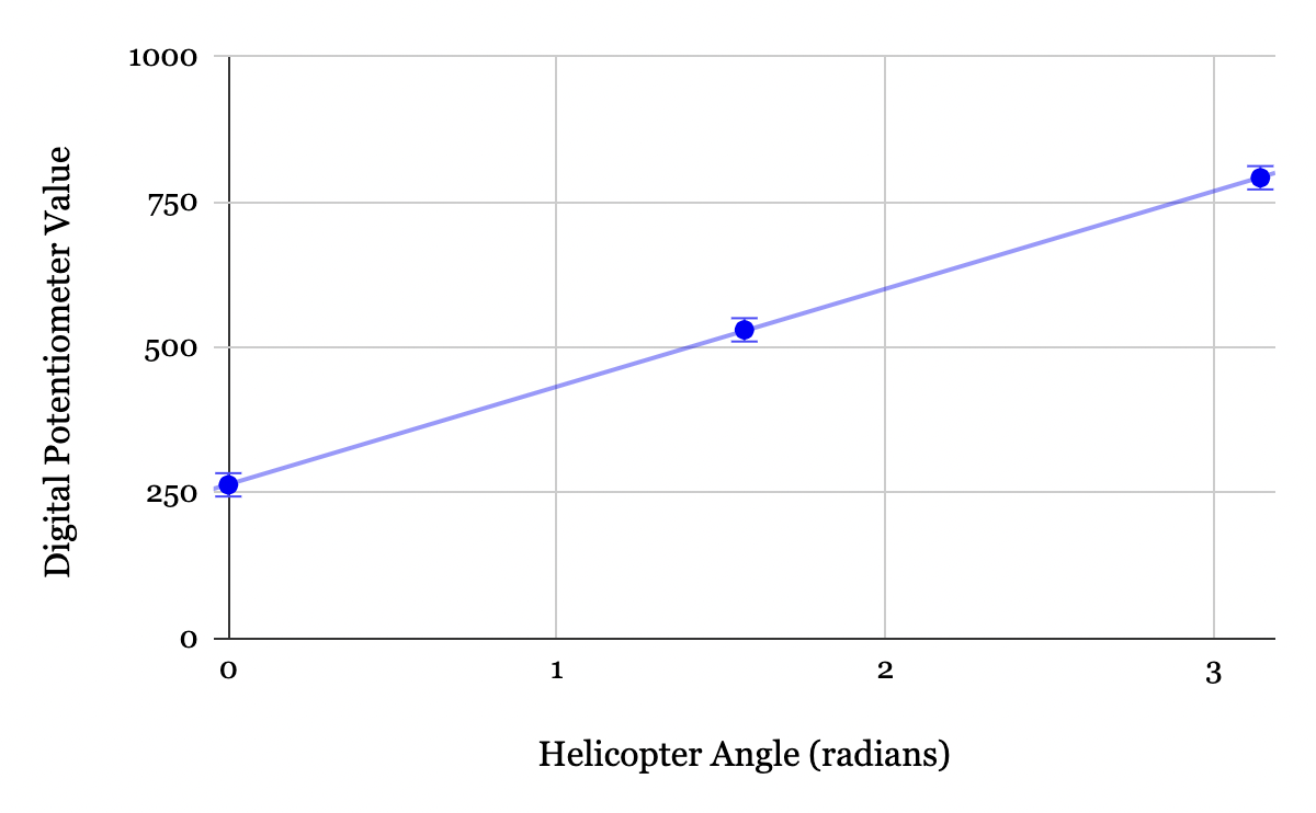 Figure 5. Data used to determine the mapping from the digital potentiometer signal to the corresponding helicopter angle. The error bars increased by a factor of 100x for visual clarity. The line of best fit was found to be \(\theta = 0.00595 * \text{value} - 1.5708\) radians with an uncertainty of \(\pm\) \(0.7^{\circ}\).
The mechanical apparatus, circuitry, and potentiometer mapping described above are sufficient to design a controller on the Arduino. The angle is encoded by an analog potentiometer signal, sent through the ADC, and converted to an angle via the potentiometer mapping function. The PWM signal controls the amount of current that passes through the motor. Thus a controller that takes in the potentiometer signal and outputs a PWM signal can be designed to enable the helicopter’s hover angle to match a user-defined reference angle.
IV. Implementation of PID
The recipe used to implement the controller was adapted from the advice provided by [3]. The recipe employs a “trial and error” method in which values are chosen until the desired outcome is achieved. The proportional gain was set whilst the integral and derivative gains were set to zero. The integral gain was then set, and lastly the derivative gain. The integral gain was chosen for steady-state error to go to zero. The derivative term was incorporated to minimize overshoot, ultimately allowing the controller to be more robust.
Proportional Term
The proportional gain was set first by finding a gain that was small enough for oscillations to settle within 3.0 seconds and simultaneously amount to the smallest rise time within bounds set by the settling time requirement. A reference angle of \(90^{\circ}\) was used when determining a value for \(K_p\). Figures 6, 7, and 8, show corresponding output for \(K_p\) values of 50, 100, and 200, a reference angle of \(90^{\circ}\). Other gains were experimented with, but these specific gains were selected to illustrate the key findings.
The plots demonstrate how increasing \(K_p\) will correspond to more overshoot and longer settling time, but with a faster rise time. Fig. 6 and Fig. 7 both reach steady-state within 3.0 seconds. On the other hand, Fig. 8 has oscillations for nearly the first 10 seconds, with amplitude ranging from \(0^{\circ} - 60^{\circ}\). From this, it is concluded \(K_p = 200\) is too large of a proportional gain to reach the settling time requirement. Though \(K_p = 50\) satisfied the settling time requirement, its rise time was 0.8 seconds, compared to 0.3 seconds for the \(K_p = 100\) case. Thus of the 3 \(K_p\) values in Fig. 6, Fig. 7, and Fig. 8, \(K_p = 100\) was found to be the most ideal.
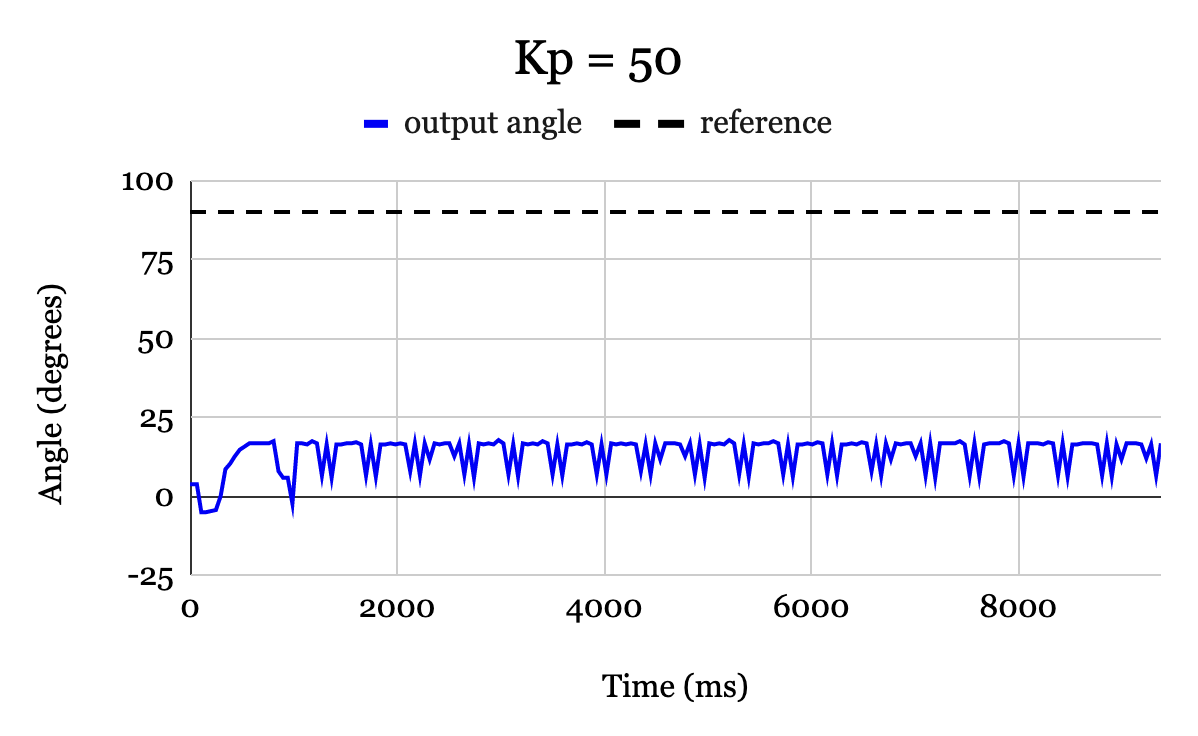 Figure 6. Output response versus time (blue) for a reference angle of \(90^{\circ}\) with \(K_p = 50\), and integral and derivative gains set to 0. The system has no observable oscillations prior to settling but outputs a large steady-error (\(75^{\circ}\)) with a slow rise-time (0.8 seconds).
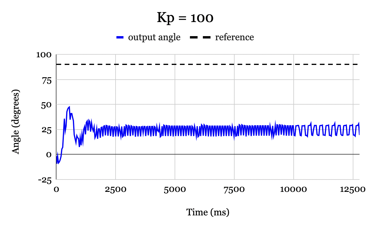 Figure 7. Output response versus time (blue) for a reference angle of \(90^{\circ}\) with \(K_p = 50\), and integral and derivative gains set to 0. The system has no observable oscillations prior to settling but outputs a large steady-error (\(75^{\circ}\)) with a slow rise-time (0.8 seconds).
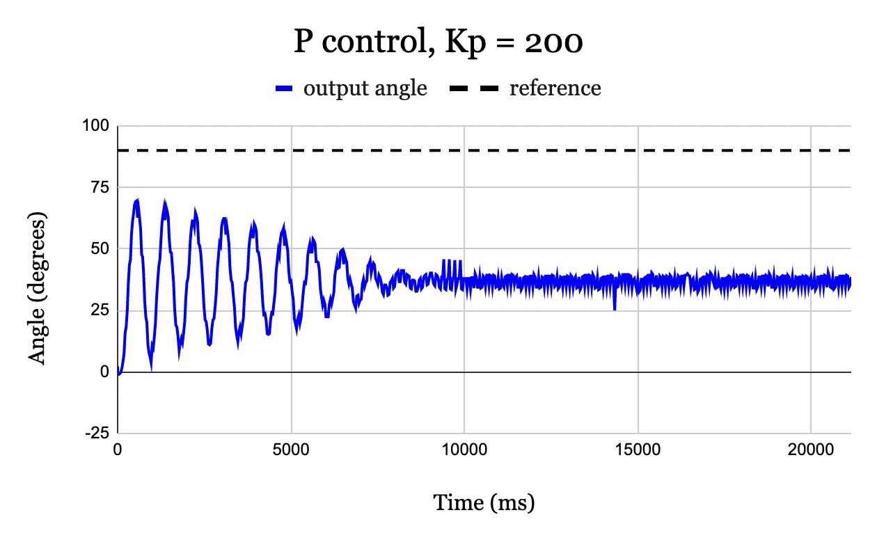 Figure 8. Output response versus time (blue) for a reference angle of \(90^{\circ}\) with \(K_p = 200\), and integral and derivative gains set to 0. The system has many oscillations prior to settling with a steady-state error of (\(53^{\circ}\)) and a very fast rise time (0.29 seconds).
Further experimentation continued to show that \(K_p = 100\) produced the most ideal results. Note that for all \(K_p\) values, there was significant steady-state error. Increasing \(K_p\) reduced this error slightly but at the expense of introducing more oscillations and a longer settling time. The reasoning for this phenomenon is discussed in Section V. \(K_p\) alone was insufficient as a controller.
Integral Term
After the \(K_p\) value was determined, the value for \(K_i\) was chosen by increasing it until the steady state error was reduced to zero. This was done with an angle of \(90^{\circ}\). The starting value was arbitrarily chosen as \(K_i = 1\) and was immediately successful in reducing steady-state error to zero. After experimentation, it was found that a value of \(K_i = 0.9\) was more effective in minimizing overshoot and was still sufficient to provide zero steady-state error. The joint PI controller with optimally determined gains is illustrated in Fig. 9.
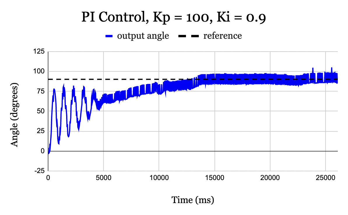 Figure 9. PI controller with \(K_p = 100\) and \(K_i = 0.9\) for a reference of \(90^{\circ}\). With integral control, steady-state error is 0.
Though the PI controller worked effectively for an input angle of \(90^{\circ}\), as the reference angle increased above \(90^{\circ}\), it became less robust to disturbances. Disturbances may include gusts of air or signal delays. Fig. 10 demonstrates the response of the system with a reference angle of \(120^{\circ}\). The system has two cycles of oscillations around the desired angle, but is unable to recover after a third oscillation and rises above \(180^{\circ}\). At higher angles, the system is more sensitive to overshoot. The underlying physics that cause this are discussed in Section V. Derivative control is implemented to minimize overshoot, thereby allowing for a wider range of angles the controller accepts.
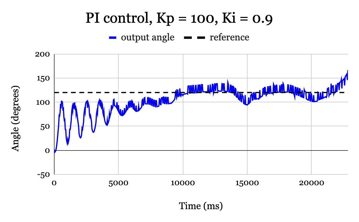 Figure 10. PI controller with \(K_p = 100\) and \(K_i = 0.9\) for a reference of \(120^{\circ}\). The controller is unable to stabilize the system, and the helicopter flies above \(160^{\circ}\) and eventually flips over \(180^{\circ}\) (not pictured due to automatic shut-off at \(170^{\circ}\)).
Derivative Term
The derivative gain was experimented with at a reference angle of \(\theta = 120^{\circ}\). The PI controller was effective for reference angles below this, thus derivative gain was added with the goal of increasing controller robustness and ultimately allowing the controller to work for a wider range of reference angles.
When the derivative term was initially added for a value of \(K_d = 1\), the output looked identical to the output from the PI controller in Fig. 10; the system remained largely unaffected by this term. The gain was increased up to \(K_d = 500\) until a noticeable difference was encountered. However, rather than becoming more robust, as was intended, the controller was far more sensitive to noise. This caused the output angle to move sporadically. To diagnose the issue, the controller output PWM signal contributions from each term were plotted versus time, shown in Fig. 11. Even with a derivative gain \(K_d = 500\), the derivative term is averaged around a PMW signal of 0. The average only slightly drops off after 12.5 seconds. More importantly, the noise in the derivative term compared to that of the proportional and integral terms is extremely high. The reason for the noise introduced by the derivative term will be discussed in Section V.
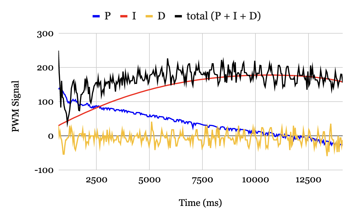 Figure 11. Proportional, integral, and derivative contributions (blue, red, gold) and the total output signal (black) versus time. Proportional and integral contributions have very little noise. Derivative contribution is extremely noisy and yielding an average value of approximately zero for the duration of data collection.
The noise of the derivative term was reduced by applying a moving window average to the error prior to differentiating it. Rather than taking a given data point as the absolute value, the value for at a given instant is given by the average of the previous \(n\) measurements, where \(n\) is the size of the “window”. This has the effect of smoothing noisy data [5]. Fig. 12 shows the result of applying a moving window average of size \(n = 6\) to the data.
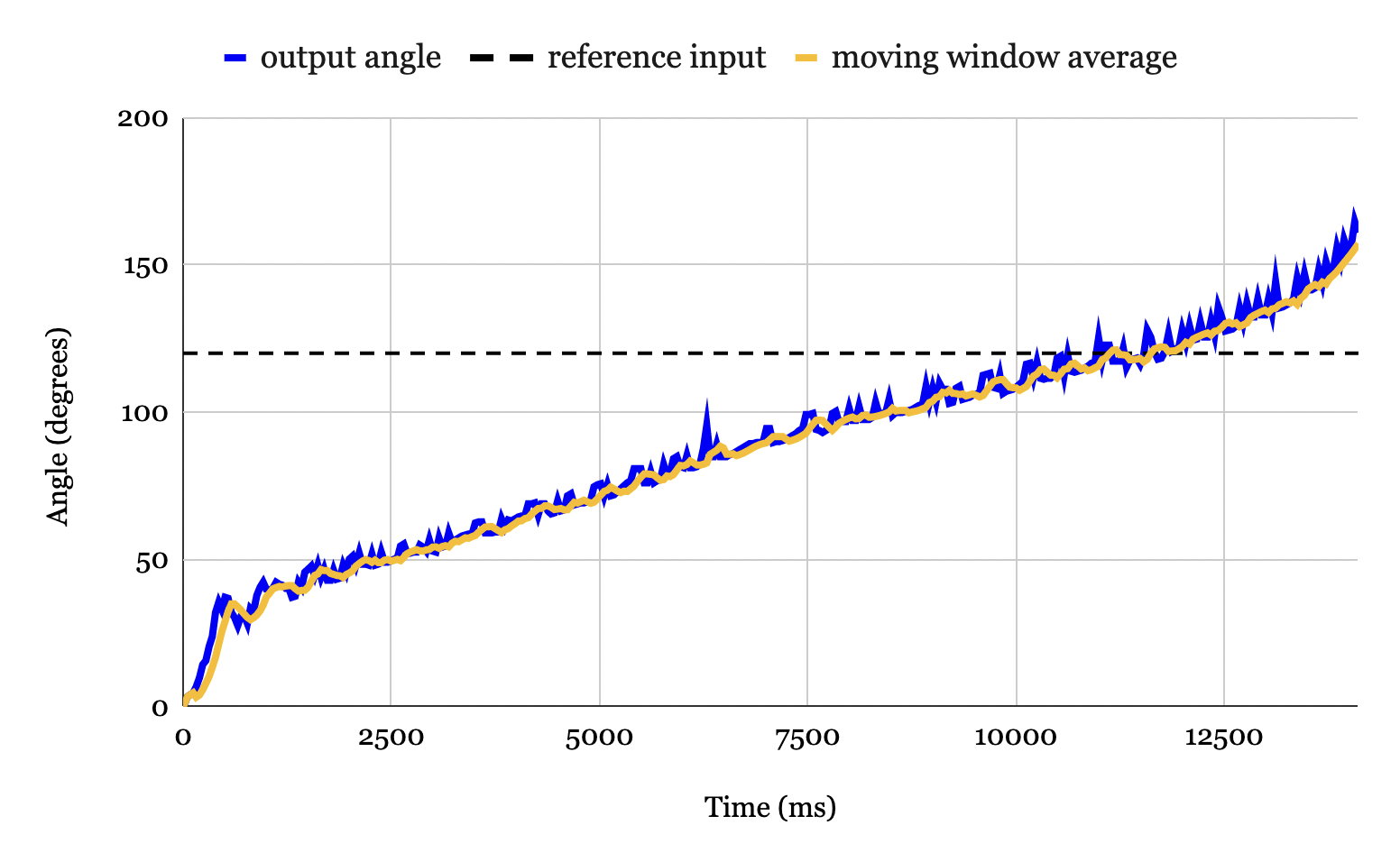 Figure 12. Output angle vs time for \(K_p = 100\), \(K_i = 0.9\), and \(K_d = 500\). The raw data form of the output angle (blue) is extremely noise, with high and frequent spikes. The output angle to which a size \(n = 6\) moving window average was applied (gold) is much smoother, with smaller and less frequent peaks.
By feeding the “smoothed” data into the D controller, derivative control worked as desired, ultimately allowing the controller to work for higher angles. Fig. 13 shows the controller working for a reference angle of \(125^{\circ}\). The output angle is very stable and stays within \(\pm\)2 degrees of the reference input.
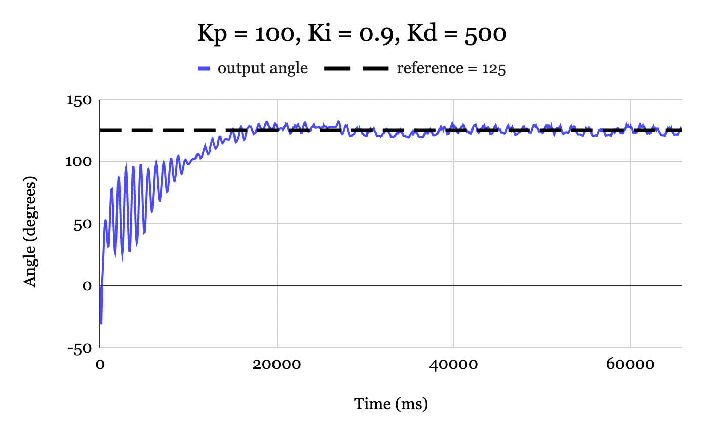 Figure 13. PID controller with D control using a moving-window-average of size \(n = 6\) for a reference of \(135^{\circ}\). The error stabilizes to within \(\pm 2^{\circ}\) of the desired reference.
The PID controller for a reference of \(135^{\circ}\) is shown in Fig. 14. Though the controller was able to stabilize the system at this reference angle, the oscillations around the reference input are higher than those for the \(125^{\circ}\) case. The reasoning for this, as well as additional methods to deal with it, are discussed in Section V.
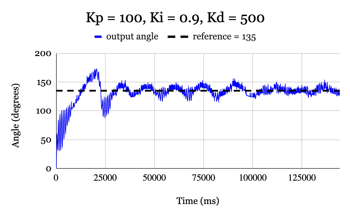 Figure 14. PID controller with D control using a moving-window-average of size \(n = 6\) for a reference of \(135^{\circ}\). The error stabilizes to within \(\pm 15^{\circ}\) of the desired reference.
V. Discussion
The effectiveness of the P, PI, and PID controllers discussed previously are summarized in Table II.
| Controller | Gain Values | Range of Angles |
|---|---|---|
| P | $$K_p = 100,~K_i = 0.0,~K_d = 0.00$$ | N/A |
| PI | $$K_p = 100,~K_i = 0.9,~K_d = 0.00$$ | $$0^{\circ} - 115^{\circ}$$ |
| PID | $$K_p = 100,~K_i = 0.9,~K_d = 500$$ | $$0^{\circ} - 135^{\circ}$$ |
Table II. Effectiveness of Different Controllers
Proportional control was insufficient in producing an output angle that matched the reference. As the error decreased, the output PWM signal decreased proportionally. In this system, the steady-state error occurs at a point when the thrust torque provided by the motor is in equilibrium with the torque due to gravity. For example, Fig. 15 shows the output angle and the output PWM signal on the same plot for \(K_p = 100\). At around 2.0 seconds, we see that a PWM signal of 100 causes the motor to thrust at a force exactly equal to the torque due to gravity when the angle is at around \(25^{\circ}\). Since the two are in equilibrium, the error is constant, and the output PWM signal therefore remains fixed. This phenomenon will occur regardless of the reference angle or the proportional gain [6]. Integral control must be introduced to eliminate steady-state error.
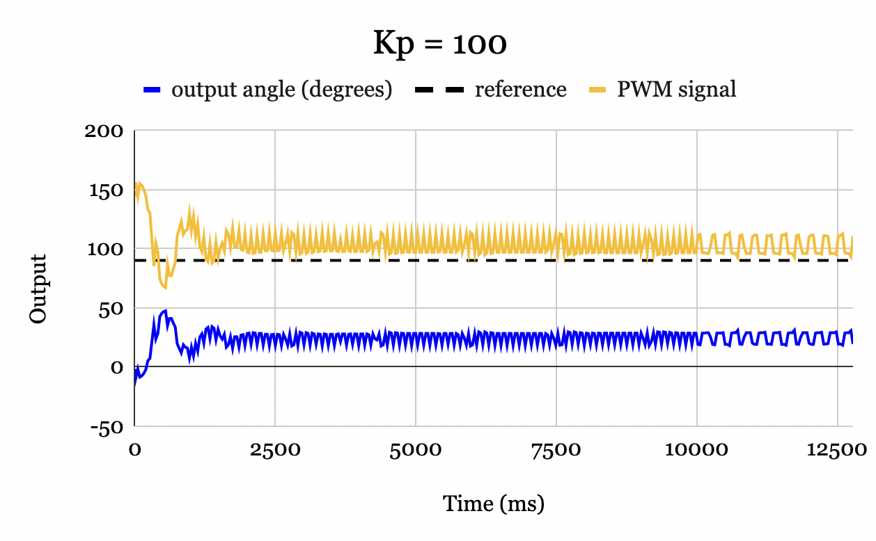 Figure 15. Output angle in degrees and PWM signal versus time for a P controller with \(K_p = 100\) and reference of \(90^{\circ}\). At approximately 3 seconds, the thurst torque is in equilibrium with the gravitational torque, and the PWM signal and error therefore remain perpetually fixed with a nonzero steady-state error.
Integral control reduces the steady-state error to zero by accumulating the error over time. Unlike proportional control, integral control produces a non-zero output signal even for an input error of 0. Fig. 16 illustrates how proportional and integral control sum together to produce an output PWM signal that enables the steady-state error to reach zero. As the error reduces over time, the proportional control gradually falls to zero. However, the integral control is nonzero due to the error that was accumulated over the first ~12 seconds. This ultimately allows the final PWM output signal to produce a thrust torque equal to the torque due to gravity at the desired angle, enabling the steady-state error to be maintained at zero.
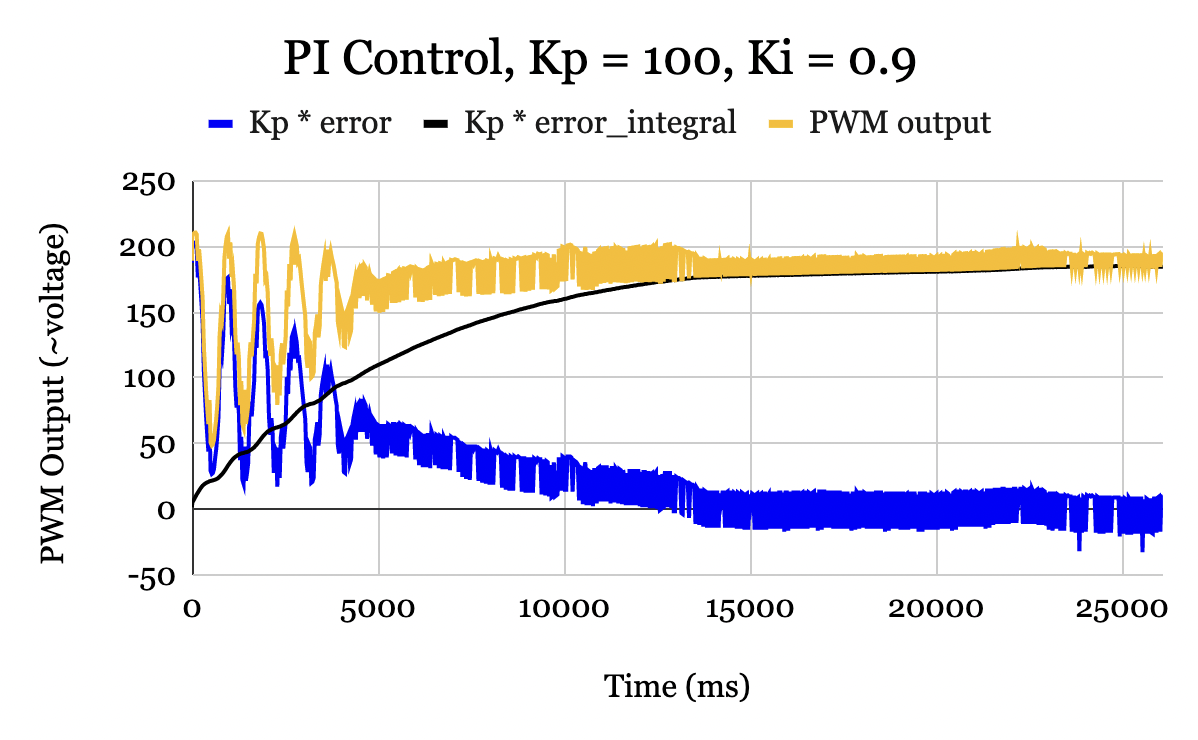 Figure 16. PWM outputs for a PI controller with \(K_p = 100\) and \(K_i = 0.9\). Proportional contribution (blue) falls to zero as the controller reaches steady-state. Integral contribution (black) accumulates over-time, allowing controller to reach zero steady-state error. Total output (gold) is the sum of the two contributions.
The PI controller was ultimately unsuccessful for angles above \(110^{\circ}\). Fig. 17 shows the 2 main forces acting on the motor (the damping force is not pictured for simplicity). One can use trigonometry to show that the torque due to gravity \(\tau_g\) is
\[\tau_g = |\vec{F}_g|\ell sin\theta,\]where \(\vec{F}_g\) is the force due to gravity and \(\ell\) is the length of the rod. For angles above \(90^{\circ}\) the gravitational torque decreases until it reaches 0 at \(\theta = 180^{\circ}\). Thus if the motor approaches an angle \(\theta > 90^{\circ}\) with sufficiently high speed, even if the motor is turned completely off, the gravitational torque may be too low such that the momentum of the motor carries it past an angle of \(\theta = 180^{\circ}\), at which point it cannot be recovered.
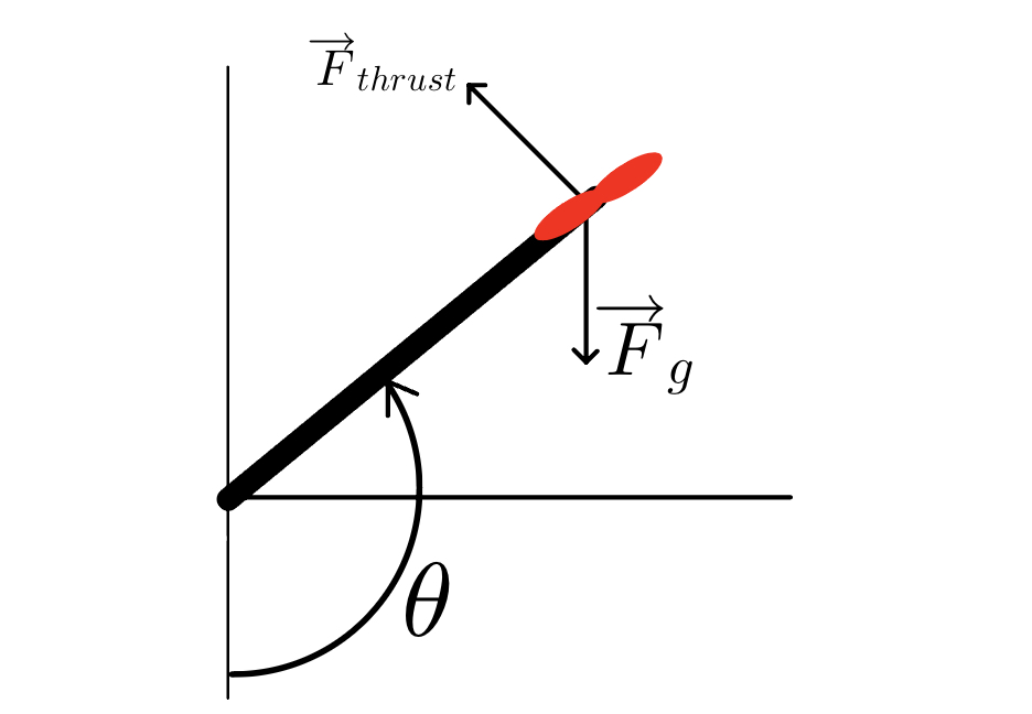 Figure 17. Free body diagram for the controller. Torque due to gravity = \(|\vec{F}_g|\ell sin\theta\), and peaks at \(90^{\circ}\) and decreases for angles \(90^{\circ} < \theta < 180^{\circ}\).
Derivative control addresses this phenomenon by reacting to the rate of change of the error. If the error is increasing or decreasing rapidly, derivative control will cause the total output PWM signal to adjust accordingly.
Even with PID control, the derivative term lost robustness at higher angles. For a reference angle of \(125^{\circ}\) the output angle stabilized within \(\pm 2^{\circ}\) of the desired angle. For a reference of \(135^{\circ}\) the output angle stabilized within \(\pm 10^{\circ}\), demonstrating it was much more sensitive to noise. This again can be related to the free body diagram in Fig. 17. The larger angle corresponded with less gravitational torque, causing the output thrust to be the dominating term. Due to this, the output PWM signal was more sensitive to small disturbances, such as air gusts, causing a higher amplitude of oscillations.
The derivative term was also shown to introduce additional noise into the system. This can be explained mathematically. Consider a noisy error represented as a sine wave with frequency \(\omega\) and amplitude \(e_0\):
\[e(t) = e_0 \sin (\omega t).\]The contribution from derivative control will therefore be
\[\frac{d}{dt}e(t) = e_0 \omega \sin(\omega t).\]Thus for high-frequency signals, such as noise, adding derivative control will increase the amplitude by a factor of the frequency \(\omega\). The moving window average allowed the noise to be reduced via a software implementation and was a simple way to effectively implement D without changing the circuitry. However, considering the derivative control is amplified by a factor \(\omega\), implementing a low pass filter would effectively reduce additional noise introduced by differentiating.
A low-pass filter allows the low-frequency signals to be captured while throwing out high frequencies. The low-frequency oscillations of the potentiometer are more likely to correspond with the actual state of the physical system, and therefore are necessary when calculating error. On the other hand, high-frequency signals are more likely to correspond to noise, and therefore are unwanted. Implementing low-pass filters is a common way to reduce noise in a PID controller in which derivative control is necessary.
VI. Conclusion
This paper discussed the method and results of implementing a PID controller on a 1-DoF helicopter. The PI controller alone was effective for angles up \(110^{\circ}\). Adding derivative control increased robustness, allowing it to be effective up to \(135^{\circ}\). Methods to deal with noise introduced by derivative control, including moving-window-average and low-pass filters, were discussed.
Additional methods of control design include frequency-domain control design and pole placement. However, these methods require linear systems. Since the system was shown to be nonlinear (\(\sim \sin \theta\)), these methods were not of use. PID tuning allows for one to design a controller without relying on a physical model of the system. The project ultimately demonstrated how PID controllers are an effective way to implement feedback control in a system where the physical hardware is accessible and can be tuned.
Acknowledgements
This project was adapted from a former ECE 4760 project designed by Hunter Adams and Bruce Land. I would like to acknowledge Hunter Adams for providing the inspiration for the project as well as the necessary hardware components. I also wish to acknowledge the support of my lab advisor Professor Bazarov for guiding me through the PHYS 4410 project and answering my questions throughout the process.
Bibliography
[1] V. Hunter Adams. “PID of a 1D Helicopter”. In: Cornell University ().
[2] Arduino - DC Motor. Available at link
[3] Driver PID Settings. Available at link
[4] B. Goodwine. “AME 437: Control Systems Engineering”. In: University of Notre Dame (2000).
[5] Jose Luise Guinon et al. Moving Average and SavitzkiGolay Smoothing Filters Using Mathcad. Tech. rep. Valencia, Spain.
[6] Steady State Error. Available at link